
Flange Inspection: From Traditional Measurement to Digital Evolution with FlangeVision
Flanged joints remain one of the most common—and most failure-prone—interfaces in industrial facilities. Whether in refineries, chemical plants, power generation, mining, or pulp and paper operations, flange flatness directly impacts gasket performance, bolted joint integrity, emissions control, and plant reliability.
Despite this criticality, flange inspection practices have changed little in decades. Many facilities and contractors still rely on manual tools developed long before today’s tightening tolerances, emissions regulations, and production pressures.
This article explores the traditional methods of flange inspection, their advantages and limitations, and then outlines how handheld 3D scanning combined with FlangeVision software is transforming how flanges are measured, analyzed, and approved.
Traditional Flange Inspection Methods
1. Visual Inspection
Visual inspection is almost always the first step. Technicians look for Corrosion, pitting, dents, or gouges, Gasket residue or surface contamination and obvious damage to raised faces or RTJ grooves. While this inspection method Fast and inexpensive and requires minimal tools, it is highly subjective and technician-dependent, and cannot quantify flatness, warpage, or thickness and often misses subtle deformation that leads to leaks.
Bottom line: Visual inspection is necessary—but entirely insufficient on its own.
2. Straightedge and Feeler Gauges
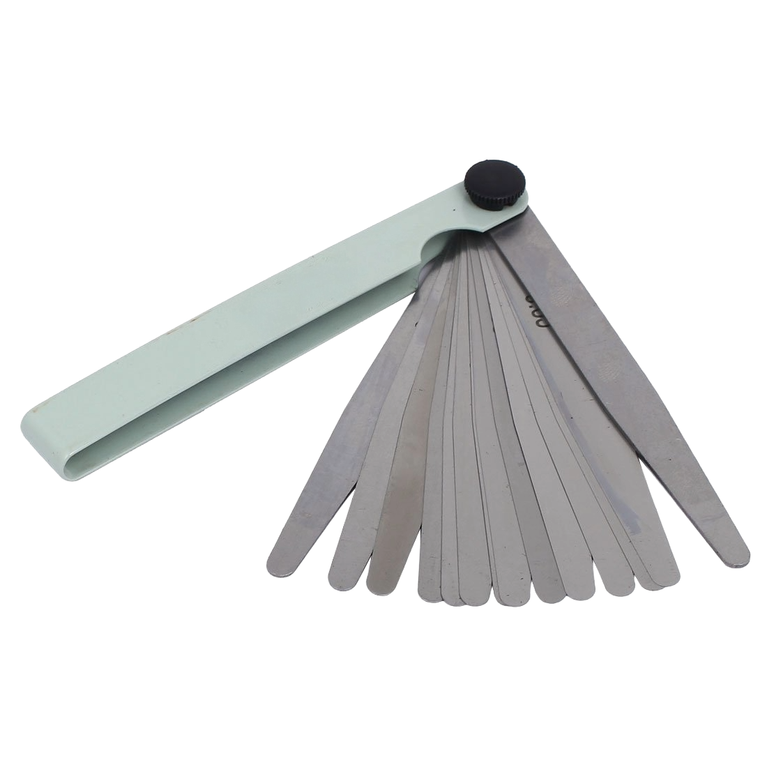
This method involves using a precision straightedge, placed across the flange face in multiple orientations (radial, circumferential, and diagonal). Feeler gauges are then inserted beneath the straightedge to measure gaps, which are compared against allowable tolerances (e.g., ASME PCC-1 guidance). This method is low cost, simple and widely understood and is suitable for small, accessible flanges.
Measurements are only taken along limited lines—not the full surface and misses localized high or low spots between measurement lines. the accuracy depends heavily on straightedge quality and operator technique. This method can be especially time-consuming on large and/or obstructed flanges.
Bottom line: Provides a partial picture of flange condition and often underrepresents the true surface geometry.
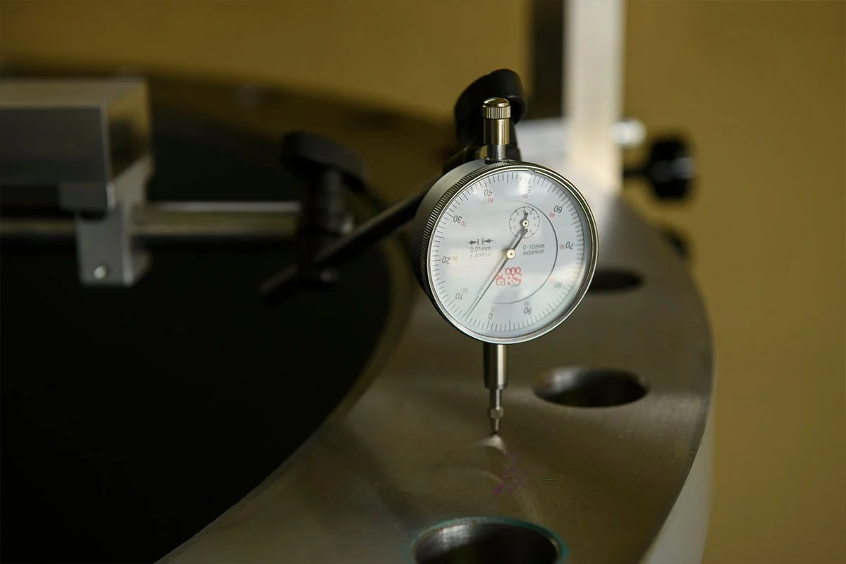
3. Dial Indicators and Bridge Gauges
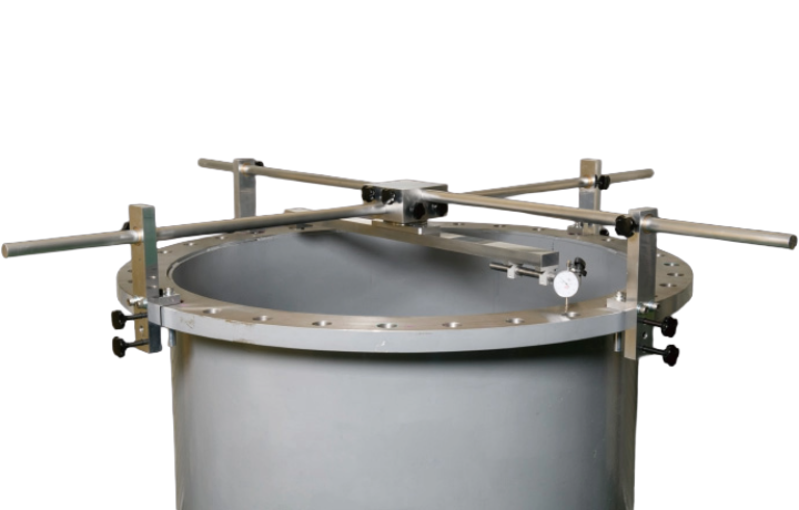
Dial indicators mounted on bridges or magnetic bases are swept across the flange face to measure deviation from a reference point or plane. This method is often used for larger flanges or during flange-facing operations. while this method provides higher resolution than feeler gauges, and is useful for verifying runout during machining, it is still limited to discrete measurement points. also, it the equipment setup is very time-consuming, sensitive to movement and difficult to use in congested or elevated locations.
Bottom line: More precise than straightedges, but still slow, subjective, and incomplete.
Summary of Key Limitations of Traditional Methods
Across all traditional techniques, several challenges consistently appear:
Incomplete surface coverage – only small portions of the flange are measured
Human variability – results depend on technician skill and judgment
Slow inspection cycles – inspection often becomes a schedule bottleneck
Poor documentation – handwritten notes or sparse data lack traceability
Disputes and rework – unclear results lead to unnecessary machining or leaks
As facilities push for tighter emissions control, shorter outages, and higher reliability, these limitations become increasingly costly.
The Digital Evolution: 3D Scanning for Flange Inspection
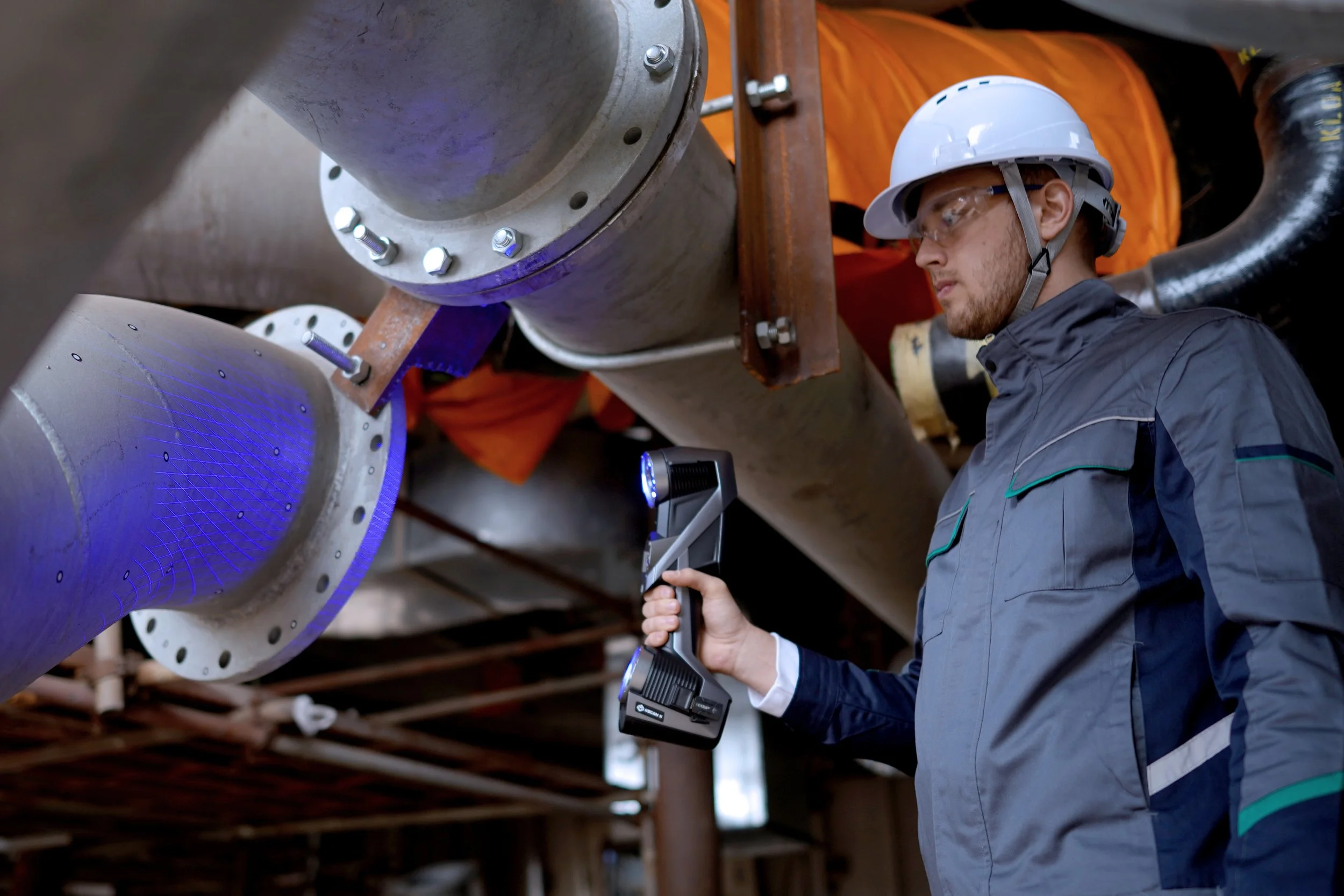
How Handheld 3D Scanning Works
Handheld 3D scanners capture thousands to millions of data points per second, creating a full digital representation of the flange surface. The scan captures:
Entire sealing surface geometry
Raised-face height and uniformity
Overall flange thickness
Localized defects, warping, and dish
The process is non-contact and minimally sensitive to access constraints. most notably, this method is FAST, with Typical scan times for a flange of 2–5 minutes.
FlangeVision: Purpose-Built Flange Analysis Software
While handheld 3D scanning captures highly accurate surface data, the real value lies in how that data is interpreted. Many facilities attempt to analyze flange scans using general-purpose metrology or inspection software—tools originally designed for dimensional inspection, reverse engineering, or CAD comparison. Although capable, these platforms often require extensive setup, advanced metrology expertise, custom workflows to approximate flange-specific analysis and significant time to extract meaningful flatness results.
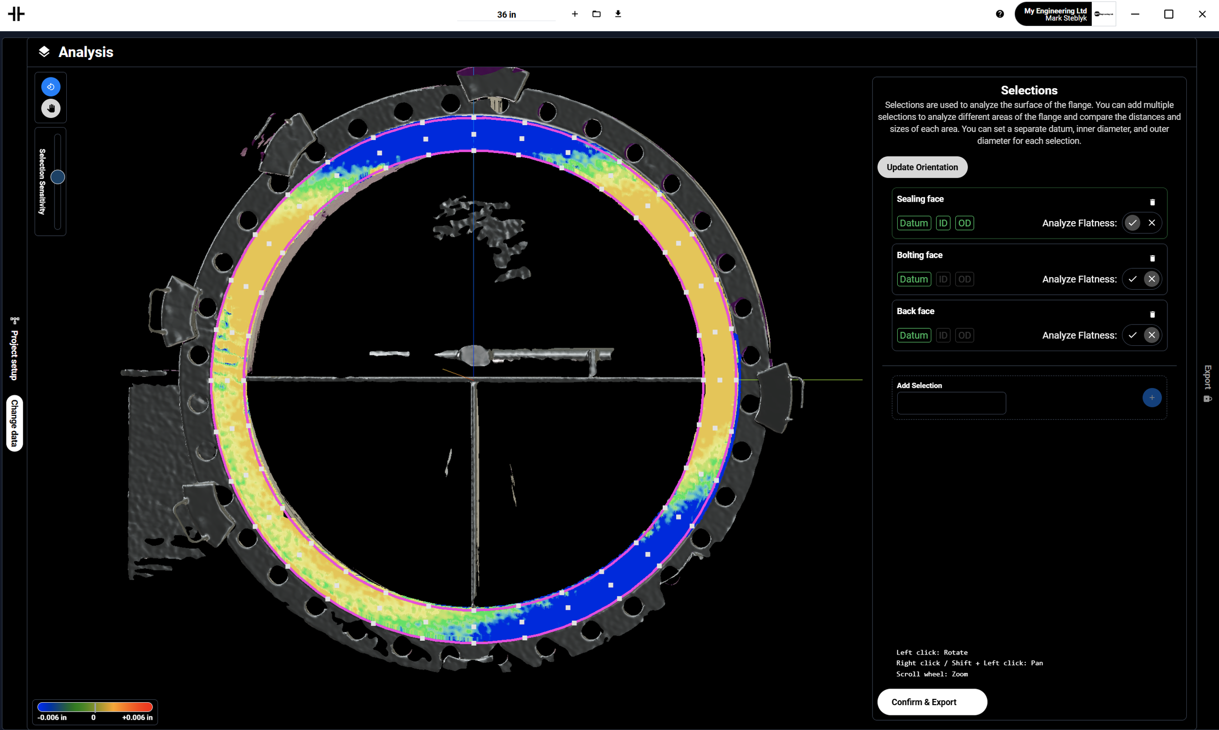
FlangeVision was developed specifically to eliminate these complexities. It is a purpose-built flange inspection platform designed around how flanges are evaluated in the field, and how owners and contractors make acceptance decisions. Instead of forcing flange inspections into generic software workflows, FlangeVision delivers flange-first analysis, turning scan data into clear, standardized, and defensible results—fast.
How FlangeVision Differs from General Inspection Software
Where general metrology software focuses on part-to-CAD deviation, GD&T callouts, or reverse engineering, FlangeVision focuses exclusively on flange integrity, gasket seating surfaces, and real-world acceptance criteria.
FlangeVision requires minimal metrology expertise, eliminates manual feature construction and complex datum schemes and delivers results that maintenance, reliability, and field teams can immediately understand.
Generic inspection software can analyze almost anything—but flange inspection demands speed, clarity, and consistency in high-pressure, high-cost maintenance environments. FlangeVision’s specialization delivers faster inspections, reduced training requirements,less interpretation risk, better alignment between field teams and engineering and clearer acceptance decisions
FlangeVision doesn’t just measure flanges—it standardizes how they are inspected, analyzed, and approved.
Benefits of 3D Scanning and FlangeVision
Complete Surface Insight: Unlike traditional methods, 3D scanning analyzes 100% of the flange surface, not just a few lines or points.
Faster Inspections, Shorter Outages: Inspection cycles are reduced from 30–60 minutes to just a few minutes per flange.
Objective, Repeatable Results: Automated analysis removes technician subjectivity.
Better Machining Decisions: FlangeVision clearly shows which flanges need machining and avoids unnecessary machining; reduces repair costs.
Digital Documentation and Traceability: Each flange inspection becomes a permanent digital record.
Improved Reliability and Leak Prevention: Accurate flatness data ensures proper gasket compression and bolted joint performance.
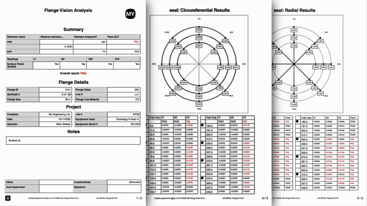
Flange Vision Flatness Report
Conclusion: From Measurement to Insight

Traditional flange inspection methods were developed for a different era—one with looser tolerances, longer schedules, and less emphasis on documentation and emissions control. Today’s industrial facilities require faster inspections, higher confidence in decisions, better documentation and reduced rework and downtime.
Handheld 3D scanning combined with FlangeVision replaces subjective measurement with data-driven insight, enabling both owners and contractors to inspect flanges with unprecedented speed, accuracy, and clarity.
Flange inspection is no longer just about measuring flatness—it’s about protecting production, reliability, and safety.